A motor encoder measures the rotation of a motor shaft and sends that information to a drive, PLC or control system. This feedback can be used to regulate speed, detect direction, control position or synchronise movement with other machinery.
Choosing a motor encoder requires more than selecting a resolution. The encoder must fit the motor mechanically, provide a compatible signal and operate reliably under the expected speed, temperature, vibration and environmental conditions.
In Norway, motor encoders may also be described as pulsgivere. Enco Nordic supplies SCANCON encoder solutions for industrial motors and can assist with both new installations and replacements.
Start by defining what the control system needs to measure: speed, direction, relative movement or absolute position. Then determine whether the motor requires a solid-shaft or hollow-shaft encoder.
Before ordering, verify the shaft or bore diameter, available mounting space, maximum speed, required resolution, supply voltage, output signal, connector and environmental protection. For a replacement encoder, start with the existing part number and label rather than selecting from resolution alone.
A motor encoder converts shaft rotation into an electrical signal. The control system reads this signal and uses it to determine how the motor is moving.
Depending on the application, encoder feedback can be used to:
Some motors operate without encoder feedback. This is known as open-loop control: the drive sends power to the motor without continuously measuring the actual result.
Closed-loop control uses encoder feedback to compare the requested movement with what the motor is actually doing. The system can then correct speed or position when the load or operating conditions change.
The required feedback determines which encoder principle, resolution and signal output are suitable.
For basic speed regulation, an incremental encoder is often sufficient. It generates a defined number of pulses for every shaft revolution. The control system counts these pulses over time to calculate rotational speed.
Higher pulse counts provide more measurement points per revolution, but the highest available resolution is not automatically the best choice. The controller must be able to process the signal frequency at the motor’s maximum speed.
For example, doubling the pulses per revolution also doubles the signal frequency at the same shaft speed. This must be considered when selecting the encoder and configuring the drive.
Many incremental encoders provide two output channels, commonly called A and B. These signals are offset from each other. By checking which channel changes first, the controller can determine the direction of rotation.
This arrangement is known as quadrature output. A quadrature encoder can therefore provide information about both movement and direction.
Some encoders also provide an index channel, often called Z. This produces one reference pulse per revolution and can be used for homing or establishing a repeatable reference point.
Incremental feedback shows how far the motor has moved from a known starting point. If power is lost, the controller may also lose the calculated position. The machine must then return to a reference sensor or home position after startup.
An absolute encoder assigns a unique value to each measured position. The controller can read the position after startup without first counting movement from zero.
Absolute feedback is relevant when:
The correct choice depends on what the motor control system must know.
An incremental encoder is usually the more direct solution when the main requirement is speed or direction feedback. An absolute encoder is more relevant when the controller must know the actual position immediately after startup.
The motor application still needs to be evaluated as a complete system. An absolute encoder does not solve mechanical mounting problems, and a high-resolution incremental encoder is not useful if the drive cannot process its output.
After selecting the feedback principle, the next question is how the encoder will be connected to the motor.
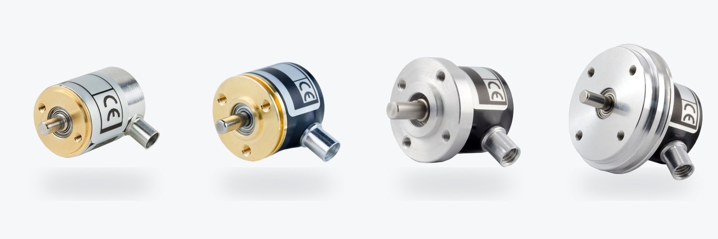
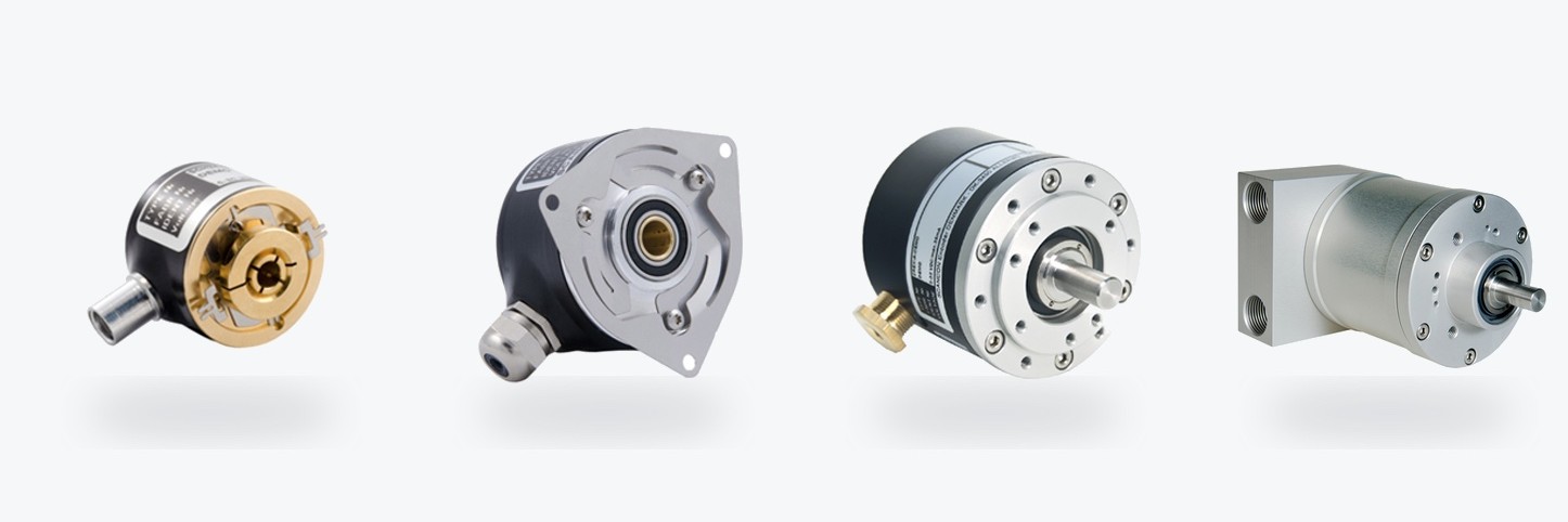
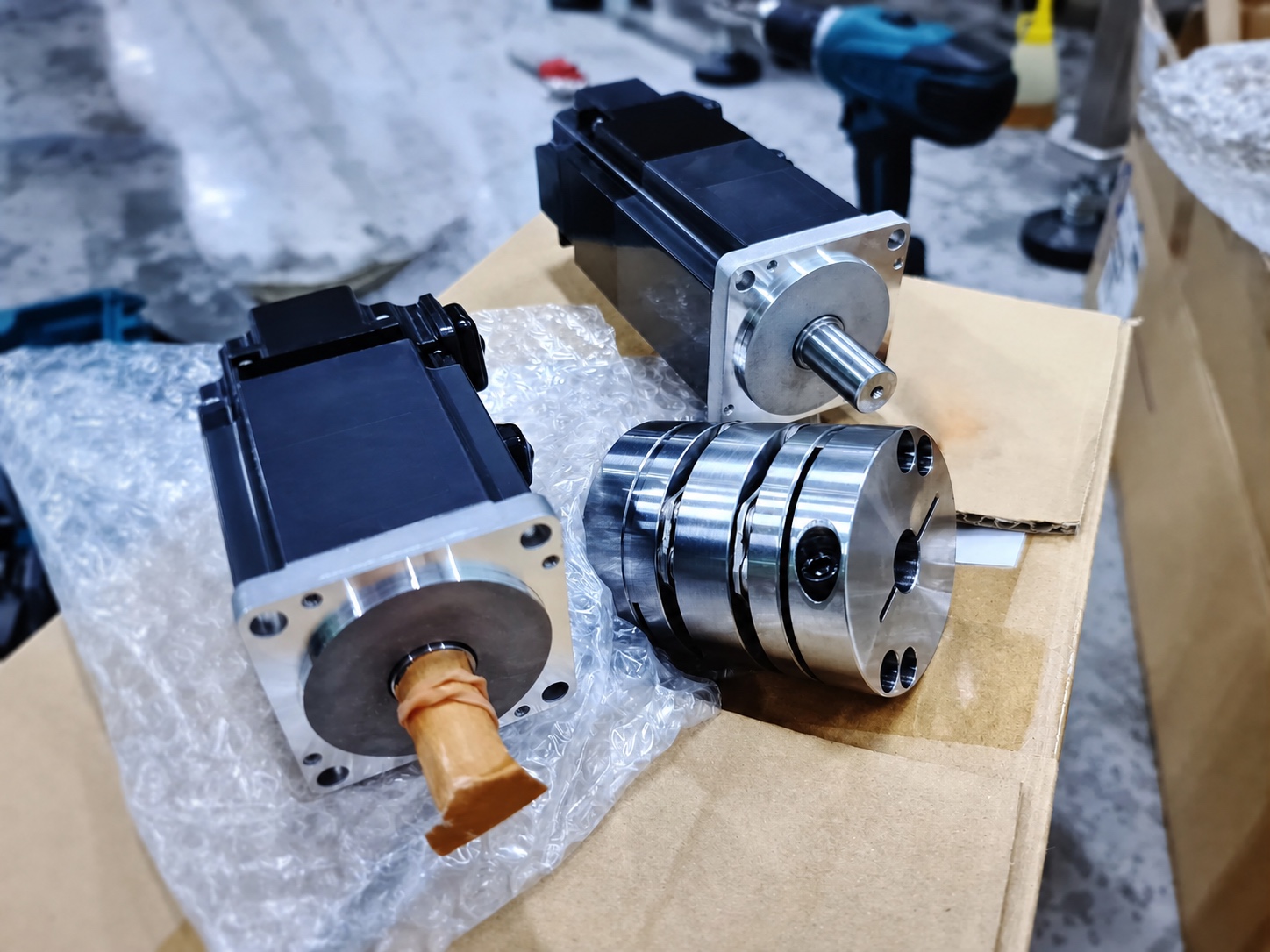
A solid-shaft encoder has its own shaft and is normally connected to the motor shaft through a coupling. The coupling transfers rotation while compensating for small alignment differences.
This arrangement can be suitable when:
Alignment still matters. Excessive angular, parallel or axial misalignment can load the encoder shaft and bearings. The coupling must be suitable for the motor speed, shaft dimensions and expected movement.
A hollow-shaft encoder mounts around the motor shaft. This can create a shorter and more compact installation because a separate external coupling is not required.

Hollow-shaft mounting is often useful when:
The bore must match the motor shaft correctly. The installation also needs a suitable anti-rotation arrangement, such as a flange, spring element or torque support. Cable clearance and access for future removal should be considered before the encoder is installed.
A motor encoder can be electrically compatible but mechanically unsuitable. Check the complete specification before choosing a model.
Confirm:
For replacements, measure the existing installation rather than assuming that encoders with the same housing diameter use the same shaft or mounting pattern.
Resolution for incremental encoders is commonly specified in pulses per revolution, or PPR. The required resolution depends on the measurement task and the controller.
Both resolution and maximum shaft speed affect the output frequency. The encoder, cable and receiving equipment must support the resulting signal.
Absolute resolution is normally specified in bits or available position values. Multiturn absolute encoders can also record the number of completed revolutions, depending on the model and interface.
The encoder output must be compatible with the motor drive, PLC or controller. Depending on the system, relevant outputs may include line-driver signals, push-pull signals, open collector, sine/cosine or an absolute communication interface.
Check:
Matching the connector shape is not enough. Two encoders can use similar connectors while having different voltage, signal or pin assignments.
Motor encoders may be exposed to heat, dust, oil, moisture, cleaning chemicals, vibration or electrical interference.
The specification should therefore include:
Applications in food production, marine environments, offshore installations or hazardous areas may require stainless steel, higher sealing or certified explosion-protected encoder configurations.
SCANCON’s motor-oriented range includes compact shaft and hollow-shaft encoders as well as standard industrial and environmentally protected configurations. The useful difference is not simply the number of available models. It is the ability to match the encoder to the motor’s dimensions and operating conditions.
For compact motors, models such as the SCA16 and SCH16F provide small shaft and hollow-shaft formats. Miniature 24 mm models such as the SCA24 and SCH24 provide additional mounting and resolution options where installation space is restricted.
Larger motor and automation applications can use standard shaft or hollow-shaft formats with higher resolution and different connector arrangements. Where the environment is more demanding, the selection may require higher IP protection, stainless steel construction or an ATEX-certified alternative.
The model name alone is not enough to select the final configuration. Shaft size, resolution, output, voltage, connection and environmental options must be checked against the relevant datasheet. SCANCON lists its applicable models on its motor industry encoder page.
Replacing an encoder requires more than finding a product with similar dimensions. Use the existing installation as the starting point.
Former product names should also be recorded. Older machinery may use an encoder designation that has since been replaced by a newer product name.
Do not assume that equal PPR values make two encoders interchangeable. An incorrect output circuit, voltage, shaft load or connector pinout can prevent operation or damage connected equipment.
To identify a suitable motor encoder, provide as much of the following information as possible:
Need help selecting or replacing a motor encoder?
Send the available motor and encoder information to Enco Nordic for assessment of a suitable SCANCON configuration for use in Norway.
A motor encoder measures the rotation of a motor shaft and sends feedback to a drive or control system. The feedback can be used to monitor speed, direction, movement or position.
No. Motors used in simple open-loop applications may operate without encoder feedback. An encoder is needed when the control system must measure actual speed, direction or position and correct the motor’s operation accordingly.
An incremental encoder is often suitable for speed and direction feedback. An absolute encoder is more appropriate when the controller must know the actual position after startup or power loss. The better choice depends on the control task.
A quadrature encoder provides two pulse signals, normally called A and B, that are offset from each other. The controller uses the order of these signals to determine the direction of rotation.
Yes, provided that the encoder bore matches the motor shaft and the installation includes suitable anti-rotation support. Available space, shaft tolerance, vibration and cable clearance must also be checked.
Start with the complete part number, label photo, shaft or bore size, resolution, supply voltage, output signal and connector. Information about the motor, maximum speed and operating environment is also important.


